- Industries
Hibbard Inshore is an underwater services company specializing in unmanned and remotely controlled operations.
- Technology
Our technology along with innovative thinking allows us to continue to deliver new ways to meet our customers’ expanding goals.
- Services
Underwater Inspection, Construction, Marine Survey & Consulting
Inverted Siphon Inspection with Crawling and Swimming Vehicles
This project was completed in a 2000 linear foot section of a 96” conveyance line that was buried under a river. The line was dry up until the point where the decline reached river level. Hibbard Inshore brought 2 vehicles to complete this inspection as a crawling vehicle alone would not have been sufficient to navigate the debris in the under-river portion of the line. A launching apparatus was attached to a crawling vehicle which was lowered into the line behind a swimming vehicle.
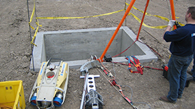
The crawling vehicle was able to push the swimming vehicle several hundred feet to the point where it could launch into the water and complete the inspection by swimming above the debris. The swimming vehicle was able to identify cracks in the concrete pipe using both video and sonar. This methodology allowed the inspection to be done without the aid of confined entry crews being several hundred feet into the line, saving significant cost. The inspection was able to be completed in a single 10 hour shift, and it led to several repair points being identified by the customer.
Tidal Generation and Managing Currents for Underwater Operations
Whether the final product is oil, gas or electricity, sometimes pipelines or cables need to span areas that are not easily conducive to underwater inspection and maintenance operations. These products are extremely important to daily life, and because of this, industry leading companies are constantly improving the equipment and methods necessary to both place these assets and to keep them in good operating condition even in the most challenging areas. Operating around swift ocean currents at depth is one of the tougher challenges presented by the location of many offshore pipelines and cables.
 Operations Control Setup
Recently, Hibbard Inshore was contracted to address the seabed assessment, site selection, and cable route survey needs for a tidal generation station in the United States which will consist of two turbines. For each project of this nature, the team assesses each unique survey location for its particular challenges in order to select the optimal vessel, remotely operated vehicle (ROV) and survey equipment spread to fit the project’s needs. The Hibbard Inshore team along with its partners has worked together for years to develop appropriate methods and equipment to address a wide variety of marine construction and inspection applications. This project was no different. The unique challenge here was that while the particular area was not very deep by ocean standards, the tidal currents in the survey area were extremely brisk. The currents had a negative effect on two earlier attempts by others to collect the necessary survey data in the proposed work area. After looking at the situation, the team decided on using a Sub-Atlantic Navajo ROV in a live-boat configuration. This meant that the ROV was run without a tether management system (TMS). The ROV system was coupled with the appropriate navigation and tracking systems for geo-referencing of the data allowing successful completion of the surveys.
 Navajo ROV and Support Equipment Loading on to Small Work Vessel
The ROV has a very high thrust to size ratio, and the live-boat configuration reduced the available cross-sectional area of the equipment allowing it to fight the current more efficiently. Further advantages of this method included the use of a small crew and small vessel. The live-boat configuration reduced the overall size and weight of the required equipment allowing the team to also reduce the size of the crew needed to operate the vessel, survey system and ROV. Additionally, the vessel did not require a mooring system or a dynamic positioning system to maintain the position of the ROV allowing for the use of a smaller (45’) vessel. Productivity was maximized because time was not required to place and move anchors across the survey area, and the ROV could be deployed very quickly to take maximum advantage of the lower current periods afforded by the change in tides. Finally, the smaller system and vessel are easy to mobilize and reduce overall associated logistical costs to the customer.
 Navajo ROV on Tail of Vessel while Underway
The survey area consisted of three separate passes of the proposed cable lay area of approximately two kilometers per pass along with a survey of the proposed area for the installation of the units which was approximately 100 meters by 150 meters where grid lines were run on ten meter centers. The nominal site depth was approximately 60 meters, and the Hibbard Inshore team was able to complete the full survey scope in three operations days making the project a success despite the difficult currents.
Inspection of Partially Flooded Interceptors and Fully Flooded Siphons
Hibbard Inshore used 2 vehicles to complete all phases of the requested inspections: a swimming vehicle to address fully flooded sections with sediment that would restrict a crawler (siphons), and a floating vehicle for partially filled lines with sediment. The sewer lines were not cleaned prior to inspection. The swimming and floating vehicles were both mobilized to site to allow for the proper piece of equipment to be used for each section of the interceptors based upon water levels. Each vehicle was deployed from the Hibbard Inshore Inspection Trailer which was backed up to each access manhole. The inspections covered approximately 42,000 feet of gravity sewer lines.
Large Diameter Partially Flooded lines
The inspection of the partially flooded lines which ranged from 48” to 120” was performed with a floating vehicle designed for large diameter partially flooded sewer inspection. The vehicle was winched either downstream or with a second hauling winch, upstream through the sewer. The distance that could be traveled was limited by obstructions, too many bends or the 5000’ length of the tether. The project access points were planned based on the supplied drawings to optimize the deployment locations to make the best use of the 5000’ range of the system.
 Hibbard Inshore Floating Vehicle on Winch
The float was configured with lighting and two cameras for the inspection above the water. One camera was a pan and tilt with zoom for close up inspection of specific features and the second camera was configured with a wide angle lens for an overall view of the sewer.
The portion of the sewer that was below the water line was inspected with two sonar units. The first sonar unit was a forward looking imaging unit to locate cracks, joints and debris. The image from the sonar could look along the invert of the sewer pipe to a range of 20’ or more depending on water depth. The second sonar was a profiling sonar that created a cross section of the underwater portion of the pipe, with sufficient water depth. The cross section could measure debris depth and invert failures.
Each access point had the air quality checked for LEL’s, CO and O2 before inserting the float. The float is waterproof and submersible but the safety of the crew and topside equipment was also considered. The float was deployed by the tether winch system at the access point. Once the float was in the flow of the sewer the tether counter was set to 0’. Then the float was winched downstream recording video, sonar and features. The data acquisition system collected the video from both video cameras as well as a video version of the sonar synchronized with the notes, date, time and tether payout. The sonar was also recorded with the native sonar program so high resolution records could be maintained. A still image of the sonar was recorded at 200’ increments and for significant features. The tether counter measured the payout in feet and the measurement was overlaid on the video and recorded within the recording system. The payout of the tether was used to locate all features within the sewer.
The float was successful in completing many long stretches of sewer including navigation around bends. This reduced the number of access points necessary and reduced disruptions to traffic in many instances. The ability of the float to move in both the upstream and downstream directions allowed for further flexibility.
 Float Passing Manhole
Flooded Siphons
The city was looking for a single inspection provider who could not only handle their partially filled, large diameter lines but also handle inspection of all of the siphons along the two interceptors. These had proven to be difficult for the city to inspect in the past because they could not be pumped down safely or effectively in many cases. Hibbard Inshore was selected because they could provide a solution to this issue and inspect the siphons while they remained fully flooded. The siphons were inspected with a swimming ROV for this project. The access into each siphon was through a chamber with a single 24” manhole access point. Air quality and the confined entry required that the entry team use surface supplied air. The chambers were vented to reduce the LEL’s to a safe level, and then the confined entry person entered the chamber at the downstream end of the siphon. The ROV was lowered through the 24” access point and the confined entry person placed the ROV into one of the siphon pipes. The ROV was capable of swimming against some flow even with sewer solids present because it was selected for its high thrust to size capabilities, but in many cases this was not necessary for this project. The three siphon tubes were at different elevations separated by weirs, and a pipe plug was used to control which siphon tubes the flow would be moving through at a given time so that the ROV could inspect each tube while its flow was blocked.
 Float Being Lowered into Manhole
The portion of the sewer that was below the water line was inspected with two sonar units. The first sonar was forward looking imaging sonar to locate cracks, joints and debris. The image from the sonar could look along the invert of the sewer pipe to a range of 20’ or more depending on water depth. The second sonar unit was a profiler unit that created a cross section of the underwater portion of the pipe, with sufficient water depth. The cross section could measure debris depth and invert failures.
Video was recorded but was able to image very little because of the turbidity of the water. The sonar was used as the primary inspection sensor. The tether payout was used to measure location of features and the 20’ increments for sonar records. The data was collected in the same data acquisition recording system as the partially flooded lines.
Confined entry permits were generated at site each day and a work sequence was followed closely for safety.
Conclusion
Hibbard Inshore was able to inspect two long interceptor lines with many bends, varying diameters, and fully flooded siphon sections. They were able to collect data both above and below the waterline to allow the city to classify the pipes in terms of their repair and replacement needs meeting the city’s overall goal for the project within the city’s projected project timeline and on budget.
Crawler Inspection of Dry Penstocks
A hydroelectric dam in the northeast United States had a planned dewatering for engineering inspection surrounding FERC relicensing and because of the steep angle of the penstocks, the engineering firm decided it would not be in the best interest of safety to perform walking inspections of these penstocks. Instead, they turned to Hibbard Inshore to conduct this interior inspection of the three penstocks using a crawling ROV with a color zoom tilt and rotate camera.
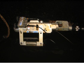
The vehicle needed to be small enough to pass through a 12”x 16” access door at the base of the surge shaft and capable of traveling up to 725’ down each penstock at a 45 degree downslope. The vehicle camera was used to follow each riveted joint to look for anomalies and also look for features of interest in each penstock section. Several features that were not on the as-built drawings were located, identified and recorded so that they could be assessed by the client’s engineering team. This inspection was able to get the customer the data they needed while allowing them to avoid a complex and possibly unsafe confined entry scenario.
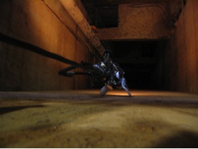
In addition to the crawling inspection of each of the penstocks, the client asked Hibbard Inshore to also devise a method for recording the conditions at the bottom of the intake as upon dewatering of the plant, audible water flow could be heard from the top of the intake structure but could not be seen. Confined entry into the intake was ruled out because the man platforms and ladders inside the intake shaft had deteriorated with time making them unsafe for their intended use. Hibbard Inshore was able to take the crawler camera, umbilical and lighting and lower it into the shaft in a manner such that the entire shaft could be seen and inspected. The camera identified piping structures at the bottom of the intake that were not on the as-built drawings and identified the source of the leak allowing the customer to keep their people out of a potentially dangerous situation.
Technology Used
Vehicle: Inuktun Crawler ROV System
Camera: Pan and Rotate Color Zoom Video Camera
Lights: Integrated air/water lights, Flood lights
Other tools equipped : 800 foot tether cable
Crawler Inspection of a Dry Tunnel with a Known Failure
Hibbard Inshore was contacted by a customer in South America to perform a dry inspection of a partially collapsed tunnel. The tunnel had already been dewatered, and a major collapsed section of the tunnel could be seen from the upstream end. The customer wanted to establish if there were additional collapses of the tunnel downstream of the known collapse so that they could plan for the tunnel repair. If downstream collapses also existed, it would stand to reason that water may be trapped between the collapsed sections making manned entry from the downstream end unsafe. So, in order to establish if there were sections of additional collapse, the client hired Hibbard Inshore to modify their large crawling remotely operated vehicle (ROV) to be able to crawl 4 kilometers through dry tunnel. The vehicle was to be able to climb over debris with up to a 12” (30 cm) shear face. To prepare the ROV for inspection, Hibbard’s team improved its stability on top of debris and lengthened its tether system. In the past, Hibbard Inshore had also used a 3D survey laser on this vehicle to determine volumes of collapsed material, but the customer determined that video would suffice in this case.
 Transition from Culvert to Tunnel
The use of an ROV allowed the client to safely identify that much of the downstream tunnel was clear although there was significant water pooling as the crawler neared the collapse region indicating an uneven grade in the tunnel. With the inspection data provided, the client was able to make informed decisions on the methods of repair that would be used to rehabilitate the tunnel.
Inspection to verify the elevation of a buried raw water intake
A client contacted Hibbard Inshore in need of an inspection of a new raw water intake pipe that had been installed to draw water out of a major river in order for it to be treated as drinking water for the surrounded community. During the installation, it was suspected that the pipe may have floated in the soft mud at the construction site potentially causing it to be out of proper alignment. The pipe was 16.5” in diameter, was fully flooded, and could not be dewatered for inspection. In order to survey the line, Hibbard Inshore proposed to use a precision depth sensor to determine the elevation of the pipeline along its distance so that it could be compared to the construction drawings. The pipeline could be accessed from a shaft on the shoreline, but the presence of bolts at the elbow into the lateral pipeline had previously prevented an inspection with a crawling ROV. Because of this, it was determined that the best way to access the line would be from the water side at the intake with divers assisting with the insertion of the ROV into the line.
Due to the relatively small 16.5” diameter of the pipe, two of the ROV’s thrusters had to be removed to fit the vehicle inside the pipeline. Hibbard Inshore marked the tether at various increments of length, using the diver to determine the ROV’s exact location within the pipe. High accuracy depth measurements were taken at regular increments to plot a profile of the pipeline along its length. Due to this inspection, the customer was able to determine that the pipeline had not had significant issues with the alignment at installation and would function as specified.
 Hibbard Distance vs. Depth
Temporary Bulkheading for Valve Replacement at a High Head Dam
This project was at a dam in the western United States where the pressure piping that would need to be plugged for valve replacement was approximately 1700’ into a diversion tunnel. This diversion tunnel has an intake structure on the bottom of the reservoir at approximately 675’ of depth. The intake structure has a trash rack that is made of concrete with steel reinforcements that could not be removed without cutting, and it was expected from previous bathymetric surveys taken from the surface that the intake would be covered almost entirely with sediment.
 Figure 6 Hibbard Inshore Modified Seabotix LBV600-6 ROV with Multiple Sensors
Hibbard Inshore worked with the customer to discuss options for inspection of the tunnel, confirmation of sediment levels, methods for accessing the tunnel, and methods for placement of a temporary plug to allow the valve replacement to be completed. The customer decided that an initial inspection would be necessary to determine the proper bulkhead design and to propose any necessary sediment removal along with a method to remove and replace a section of trash rack.
Due to the level of error in the bathymetric survey, it was agreed that in performing the initial inspection, Hibbard Inshore would bring an ROV with the capability of carrying video cameras, 2D sonar, and an ultrasonic thickness sensor while fitting between the 12” vertical gap between the beams of the trash rack, and a special tool skid would be built to transport the 3D sonar unit through this gap as well. Hibbard Inshore used its Seabotix LBV600-6 ROV to accomplish this task. Bringing an ROV prepared to swim through the trash rack bars proved to be a good decision as when the ROV descended to depth, it was shown that the primary intake was sufficiently uncovered to enable entry of the ROV. The ROV entered, travelled the 1700 feet to the pressure piping and was able to determine that each conduit could be plugged. The process also allowed the customer to consider whether both pipes should be plugged concurrently to minimize risks to each pipe from the other during the valve replacement. This inspection gave the customer the data they needed in order to have a third party engineering firm evaluate the situation and prepare recommendations to move to the construction of the project.
 Figure 7 3D Sonar Scan of 2 Pipes and Concrete Sealing Face taken by Hibbard Inshore LBV600-6
The lesson found in this project is that if you are looking to evaluate replacement of gates or valves, using a smartly outfitted ROV along with a ROV installed bulkhead is a solution that can effectively complete the project from initial inspection to final installation and removal, reduce costs versus dewatering, and can improve safety by eliminating the need for people to be in the water.
Inspection of a Dam Intake and Outlet Works Upstream and Downstream of a Spherical Valve
Hibbard Inshore was hired by a large engineering firm to inspect the intake and outlet piping of an embankment dam where access to the piping would need to be made through a blind flange in the dam control room in order to avoid a major project of removing trash racks from the intake structure which was underwater out in the reservoir. The trash rack removal would have required a commercial dive team, heavy equipment, and a longer outage period to allow access to the piping. Because the customer wanted to avoid the extra outage time and the extra costs that would entail, they determined it would be best to find an ROV company who could work with them to develop a solution to access the pipe through the blind flange. This meant that the ROV umbilical would need to pass through the flange during operations as the intake and outlet piping was reflooded and came under pressure. Once the pipe was flooded, the ROV would need to make a 600’ inspection run upstream through the spherical valve to inspect the pipe as well as a run in the downstream direction of similar length.
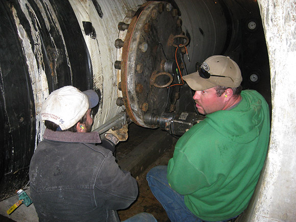
Due to the size of the 24” blind flange and the length of the inspection run, Hibbard Inshore elected to use its LBV600-6 ROV which was moved through the tunnel to the control structure room containing the spherical valve. There, a replacement blind flange was supplied by the customer with holes drilled for the installation of an electrical watertight connector and an optical watertight connector both supplied by Hibbard Inshore. The ROV tether was modified at the control console end to mate to watertight connectors. An adaptor to connect the wires on the dry side of the blind flange to the control console was also fabricated. The tether was placed into the outlet piping behind the blind flange with 600’ of slack. The 600’ was looped downstream of the access. The ROV hull was placed inside of the pipe facing the spherical valve and the blind flange was replaced. There wasn’t any leakage past the spherical valve.
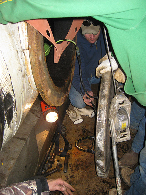
The ROV was placed facing the spherical valve so the filling progress and the effect of the filling on the tether could be monitored. This process was recorded with the video. Initially the spherical valve was opened only a small amount to the point where some water was entering the pipe. The initial velocity of the water past the ROV was high because the water depth was low. As the pipe was filled closer to half full the valve was opened further to increase the fill rate. The deeper water kept the velocity past the ROV to a manageable level.
Once the pipe was full, the spherical valve was completely opened. In the open position, it was observed that the valve didn’t have any gaps or offsets in the seals. The ROV swam upstream counting joints upstream of the spherical valve and made observations on the concrete coating. The ROV was also able to inspect the inside of the trash rack with each face of the trash rack followed to look for debris or bent bars. The LBV ROV was able to complete the entire inspection of the intake and outlet works through the blind flange. Upon completion of the inspection, the ROV tether was pulled by the ROV downstream of the spherical valve at which time the valve was closed, the pipe drained, and the vehicle was removed from the line by removing the blind flange. This method allowed the customer to successfully avoid the larger and more time consuming trash rack removal process and still achieve a successful inspection.
Long Head Race Tunnel Inspection with Mechanical Scanning and Multibeam Sonar in Low Visibility
Hibbard Inshore traveled to Central America to inspect a 9.5 meter diameter, 4.8 kilometer long, fully flooded tunnel in zero/limited visibility conditions. The tunnel had been built using several different types of material, and the inspection equipment was selected to be able to address all of these construction methods: rock cut, concrete lined and steel lined tunnel sections. To keep costs down and allow for stationary sonar measurements, the tunnel’s flow was stopped for three twelve hour outage periods to perform this imaging sonar heads and a BlueView electronic scanning head. One Imagenex sonar head took cross sections while the other was forward looking for navigation and feature detection. The BlueView sonar was also forward looking but scanned at a much faster rate in order to expedite the inspection process and still detect major features while moving.
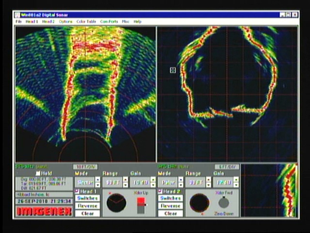
The inspection was performed in three separate dives revealing a number of blockages in several parts of the tunnel. Each dive was performed until there was too much debris to safely continue or to the terminus of the umbilical. A number of voids on the crown were identified and debris was detected throughout the tunnel utilizing the BlueView P900. During the inspection the umbilical payout was measured and once features were identified with the BlueView unit, they were cataloged with their location and the vehicle was able to quickly swim to them to try to get video confirmation despite very low visibility in the water. The inspection allowed the customer and their engineers to plan for the remediation of the issues found.
Singlebeam and SideScan Survey to Identify Sediment Buildup
A 21’ survey vessel was deployed from a marina on an inland lake in the Midwestern United States to survey an area set forth as the proposed study area to Hibbard Inshore. Survey data was collected using a single beam echosounder and two forms of side scan sonar. Attempts to collect data were also made with 2 separate frequencies of a sub-bottom profiling sonar.
There were approximately 45 data lines run 10 feet apart from one another covering approximately 1000 in linear distance to give an accurate representation of depth of the survey area. Prior to the survey, as part of the mobilization, these track lines were plotted into a navigation system on the boat, and the operator followed them in real-time during the survey. The survey was performed in calm water conditions to achieve the requested .15 foot depth accuracy, and the survey speed was kept to approximately .7 knots due to the shallow water. A bar test was performed prior to the inspection to calibrate the sensor, and both pre and post survey tests were performed each day to ensure that the sonar unit and positioning was accurate. The frequency of the sonar that was used was 200 kHz, and the data recorded was first return at that frequency.
 Singlebeam Survey Color Shaded Relief
The 2 man survey crew consisting of one hydrographic surveyor (supervisor-level, ACSM-certified hydrographer) and one boat operator and safety spotter arrived onsite and proceeded to use the Knudsen 3212 Chirp Echosounder to attempt to gather both 200 kHz singlebeam bathymetric sonardata as well as 28 kHz sub-bottom profiler data. Geographic positioning was provided via Real-Time Kinematic GPS receiving corrections from the local reference station network. After significant attempts to adjust sonar performance for the sub-bottom profiling effort, it was determined that it was difficult to get any kind of reflector to show up beneath the mudline with the sub-bottom profiler. Because of this, the survey team switched over to take the side scan sonar that day in order to allow them to re-attempt the sub-bottom profiles the following day with modified gain settings. The Tritech Starfish was used successfully to collect sidescan data.


 Inspections
