- Industries
Hibbard Inshore is an underwater services company specializing in unmanned and remotely controlled operations.
- Technology
Our technology along with innovative thinking allows us to continue to deliver new ways to meet our customers’ expanding goals.
- Services
Underwater Inspection, Construction, Marine Survey & Consulting
ROV and Divers Working Together
 Diver Preparing for Dive
Hibbard Inshore provides a wide range of ROV services. Often the optimum solution for a task is to have divers and ROVs work together, and because of this Hibbard Inshore has performed many projects in conjunction with divers. ROVs have the advantage over divers in terms of nearly unlimited bottom time, lower risk and almost no depth limitation. Divers offer a higher degree of flexibility with tooling and manual tasks. By using both techniques in a single project, the advantages of each can be used to optimize the project. The optimization is achieved by using the unlimited bottom time of the ROV for inspection while a diver is preparing to dive or decompressing. Second, if there are hazards, known or unknown, the ROV is a safer method to quantify the hazards allowing the project team to design a safe and comprehensive dive plan.
One example where commercial divers and Hibbard Inshore’s ROVs increased productivity and safety by working together was a project where a high head dam had stop logs that were leaking. In this case the bottom stop log was at a depth of 190’, and the stop logs were installed to service the head gate of a hydroelectric intake. There were two known hazards of concern to the commercial dive team; one was the differential pressure hazard created by the leak and second was the discharge of air when the head gate was lowered into place. The discharge of air was created because the head gate sealed against the upstream face and was located downstream of the stop logs. The short passage between the two didn’t have any vents and therefore trapped a volume of air between the two structures and at depths from 120’ to 190’. When the head gate was lowered into place it sealed the air. The leaking stop logs allowed water to enter the space and pressurize the air until one of the stop logs’ seals allowed the air to escape. The resulting discharge created a very large air bubble that would rise to the surface, causing turbulence. This turbulence could take a diver or ROV rapidly to the surface, and presented a safety risk to divers as this rapid ascent from depth could cause serious health issues due to rapid decompression.
 Diver Decompression Chamber
To quantify the worksite hazards and to attempt to locate the leak in the stop logs with the head gate raised, the initial inspection was performed by the ROV. The inspection plan was developed and closely followed so as not to get the ROV or tether caught in a significant leak. The ROV was able to locate the leak at the lower seal of the stop logs. The diver entered the water after the decompression chambers were setup, and the divers’ tooling was selected based on the ROV inspection. The diver descended to the work location and tested two different sealing techniques to stop the water flow. The bottom time of the diver at this depth was very limited as Mixed gas or Saturation diving wasn’t selected for the project based on cost. The diver would perform one task and return to the surface. While the diver was decompressing in a decompression chamber at the surface, the ROV was used to inspect the work to allow the dive supervisor to plan the next dive. Also, the head gate was cycled to test the temporary seals. Several dives were completed to perform all of the operations necessary to seal the stop logs.
The result of the collaboration between the ROV and diver was a successful and economical project in deep water with controlled risk to the diver.
Potable Water Transmission Line Inspections
Hibbard Inshore was contracted through a major engineering firm to inspect over 36,000’ of potable water transmission lines. The lines were to be inspected in a dry state to look for signs of wear and damage including cracking, offsets, holes or points of infiltration. Because of the lines operate under pressure, the access points were located far apart in some cases and the access diameters were small being that pressure flanges were the best option for access. Hibbard Inshore was able to address this situation by inspecting the lines with their Inuktun crawling vehicle (ROV) (Link) that had a 5,000’ tether installed for this job. The Hibbard crew inserted the ROV through the pressure flanges after the line was dewatered and monitored its umbilical payout to note the location of each feature of interest they identified. Hibbard Inshore planned each inspection run to consider the bends and elevation changes that may affect vehicle traction and the pipeline was entered from multiple access points.
Hibbard Inshore’s inspection revealed circumferential cracks, longitudinal cracks, small patches of scour, scouring at cracks, joints, air breaks, taps and manholes. Additional abnormalities including infiltration at joints, damaged patch areas, and missing concrete liner were also discovered. The location and video footage of all features were all given to the client in a detailed report after the project.
Hibbard Inshore’s ROVs were used in this case to inspect long stretches of pipeline that were difficult to access and had access points that were too far apart to be inspected with traditional equipment satisfying the customer’s needs to determine the condition of the entire length of the line.
Frequently Asked Questions
Often, Hibbard Inshore is approached by customers with questions about how to get started with their projects. When customers contact us, they range in their previous experiences with ROV inspections and construction from those who are very experienced to those looking at possibly using a robotic vehicle for the first time. We aim to bring a level of comfort to both types of customer by learning as much pertinent information about their project as possible so that an intelligent solution can be proposed. We realize that each project often has unique requirements, different driving forces, and can potentially be solved with multiple solutions. Because of this, Hibbard Inshore generally asks all of its customers a similar line of questions to determine the proper vehicle(s), sensors, tooling and methods to be used on each project. The Hibbard Inshore staff is well versed with a wide variety of inspection and construction techniques, available sensors, available electric and hydraulic tooling and of course our ROVs.
Q: What information do I need in order to get a project quote from Hibbard Inshore?
A: While Hibbard Inshore doesn’t always require all of this information, each piece of information you can give our staff about your project can help them to “sharpen the pencil” when putting together a solution and pricing. Unknowns can increase the risk and the number of scenarios that Hibbard Inshore would have to plan and prepare for.
So, with that said, general questions we may ask in order to collect helpful information would be as follows:
1. Why is the project necessary?
2. What type of data that should be gathered by the project (if the project is an inspection)?
- a. Dimensional measurement?
- b. Thickness measurement?
- c. Visual inspection?
- d. Gas measurement?
- e. Feature and anomaly detection? (cracking, out of round, sediment buildup, offsets, etc…)
- f. Geo-referencing of features?
- g. 3D mapping?
- h. Other?
3. Are there maintenance or construction goals of the project?
4. Can you provide elevation and plan drawings of the structure(s) involved?
5. What is the detail of construction material(s) of the structure(s)?
6. What are the locations of potential access points into the water, line, or structure
7. Can you provide detail of access point(s) including size or detail drawings (Manhole, Flange, Gate Slot, Surge Shaft, Intake, Hot Tap etc…)
8. What would be a suitable location and area for setup of the Hibbard Inshore electronics and recording equipment?
9. What is the maximum pressure depth of inspection or work tasks?
10. What are the flow rates that would be encountered in the work area?
11. Can the plant or line be shut down during the inspection or work?
- a. What are the associated costs of a shut down?
- b. What is the maximum duration of the shut down?
12. What will the expected visibility be during the project (zero, low, or good visibility)?
13. Where is the location of the project?
14. Are there any local operations considerations that may impact the project (permitting, fees, duties, available power for equipment, toilet facilities, traffic control requirements, difficult to reach locations, other pertinent information)
15. If known, what is the project budget or estimate?
Like we said, not all of these questions have to be answered in all situations for Hibbard Inshore to put together a method and quotation. It is just helpful to have this information to narrow options by eliminating solutions that might have potential difficulties, determine actual operating conditions, and plan for site logistics. We hope this is helpful, and if you have any questions, feel free to contact us on the phone or by e-mail at any time. We’d be happy to walk through your project with you.
The photos below are from a project where the available access point for a tunnel inspection was a surge shaft on the side of a mountain. The level of logistical difficulties seen here is atypical for our inspections, but the pictures are meant to illustrate that Hibbard Inshore’s equipment can be set up in some of the most difficult circumstances if there is good reason. Hibbard Inshore worked through the questions above with their customer to determine the project equipment and logistical requirements for their inspection. Through that process a method for inspection without dewatering was developed for a tunnel that was previously unable to be inspected.
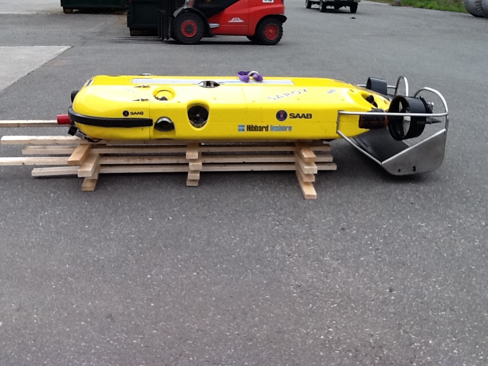
Figure 1:
Hibbard Inshore Saab Long Range Tunnel Inspection Vehicle for In-Flow Inspection
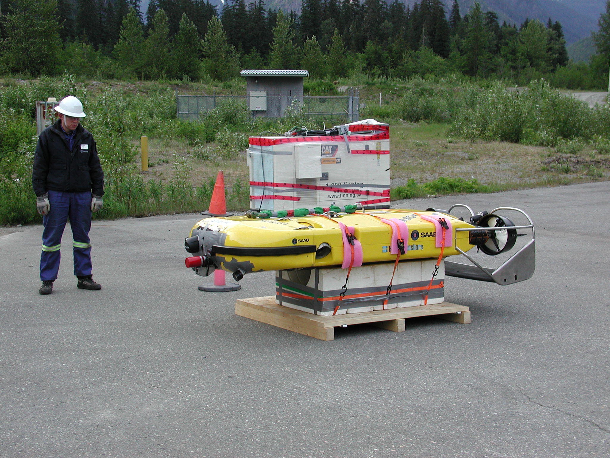
Figure 2:
Hibbard Inshore Saab Vehicle Readied for Helicopter Transport to Jobsite
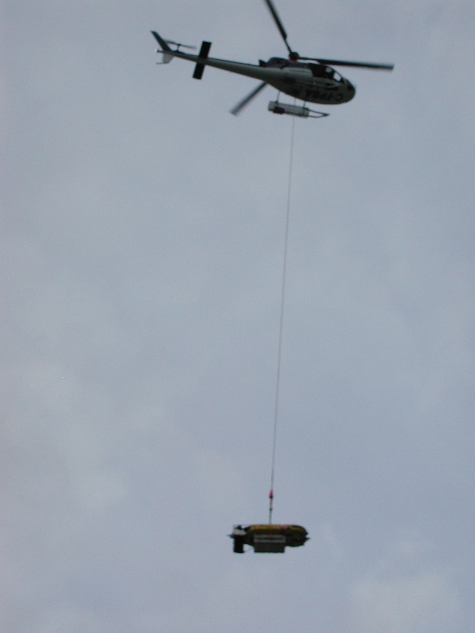
Figure 3:
Vehicle Transport to Jobsite
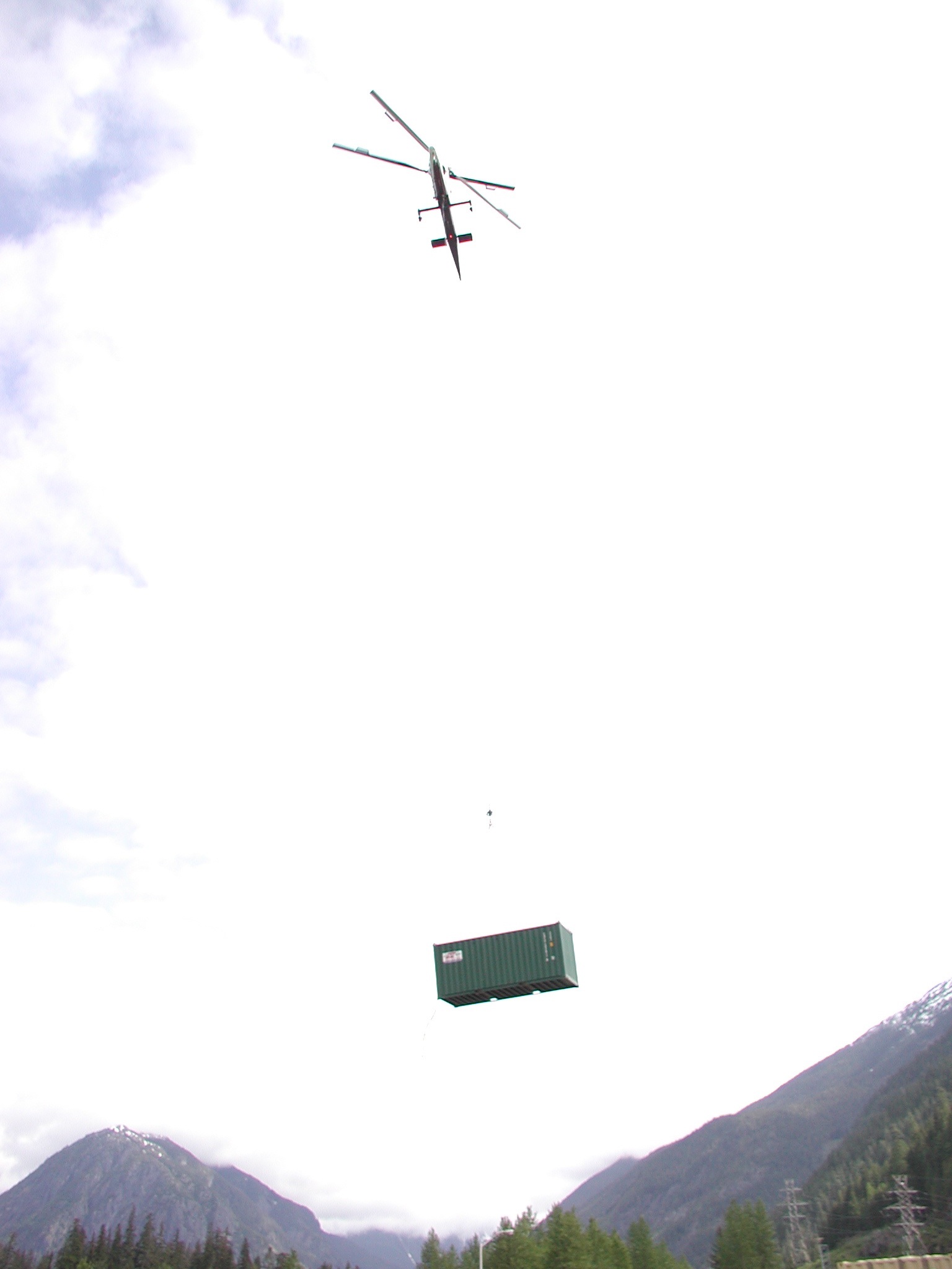
Figure 4:
Container for Jobsite Office Space
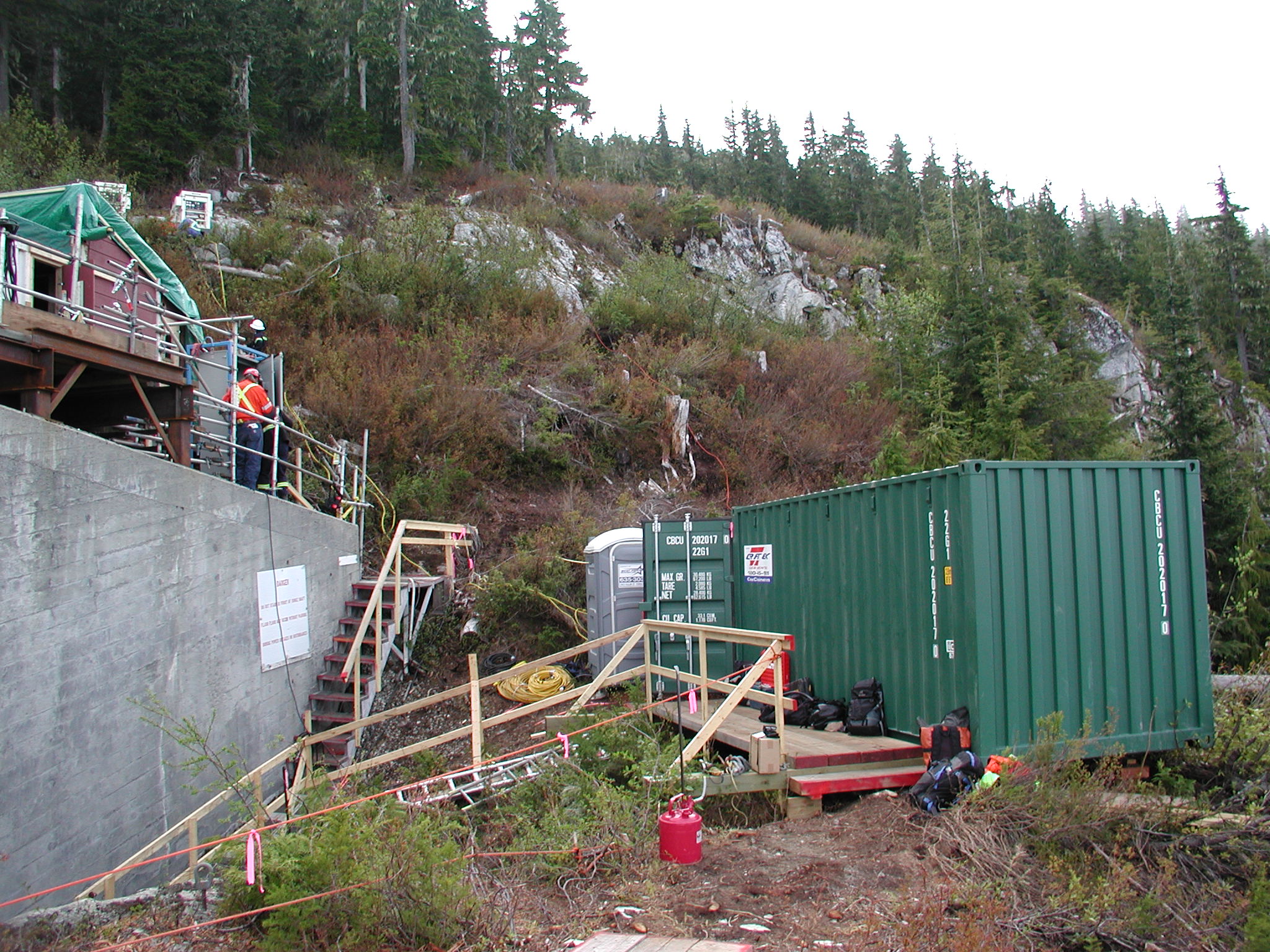
Figure 5:
Site Setup for Hibbard Inshore Remote Inspection Operations
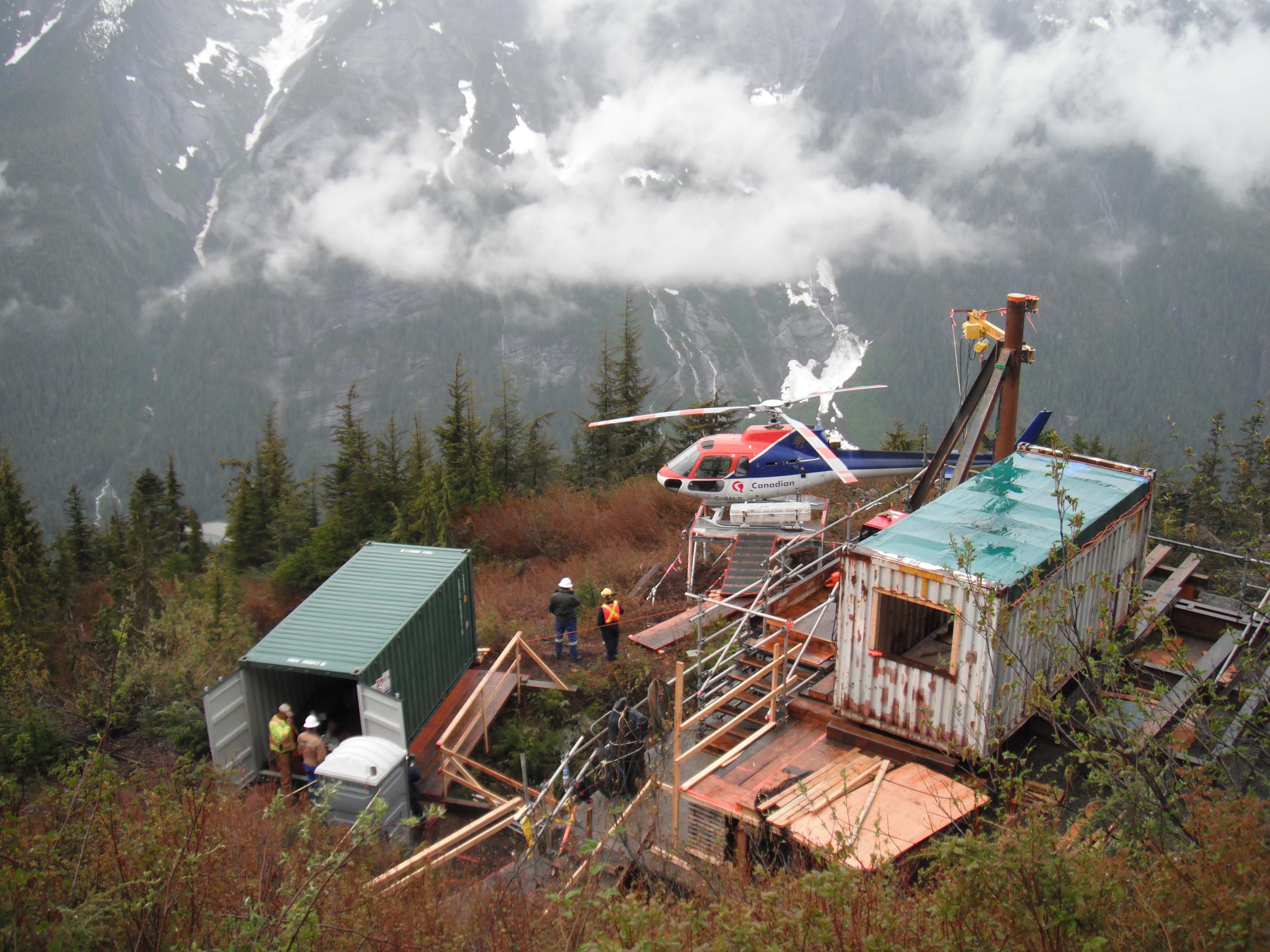
Figure 6:
Hibbard Inshore Remote Job Site
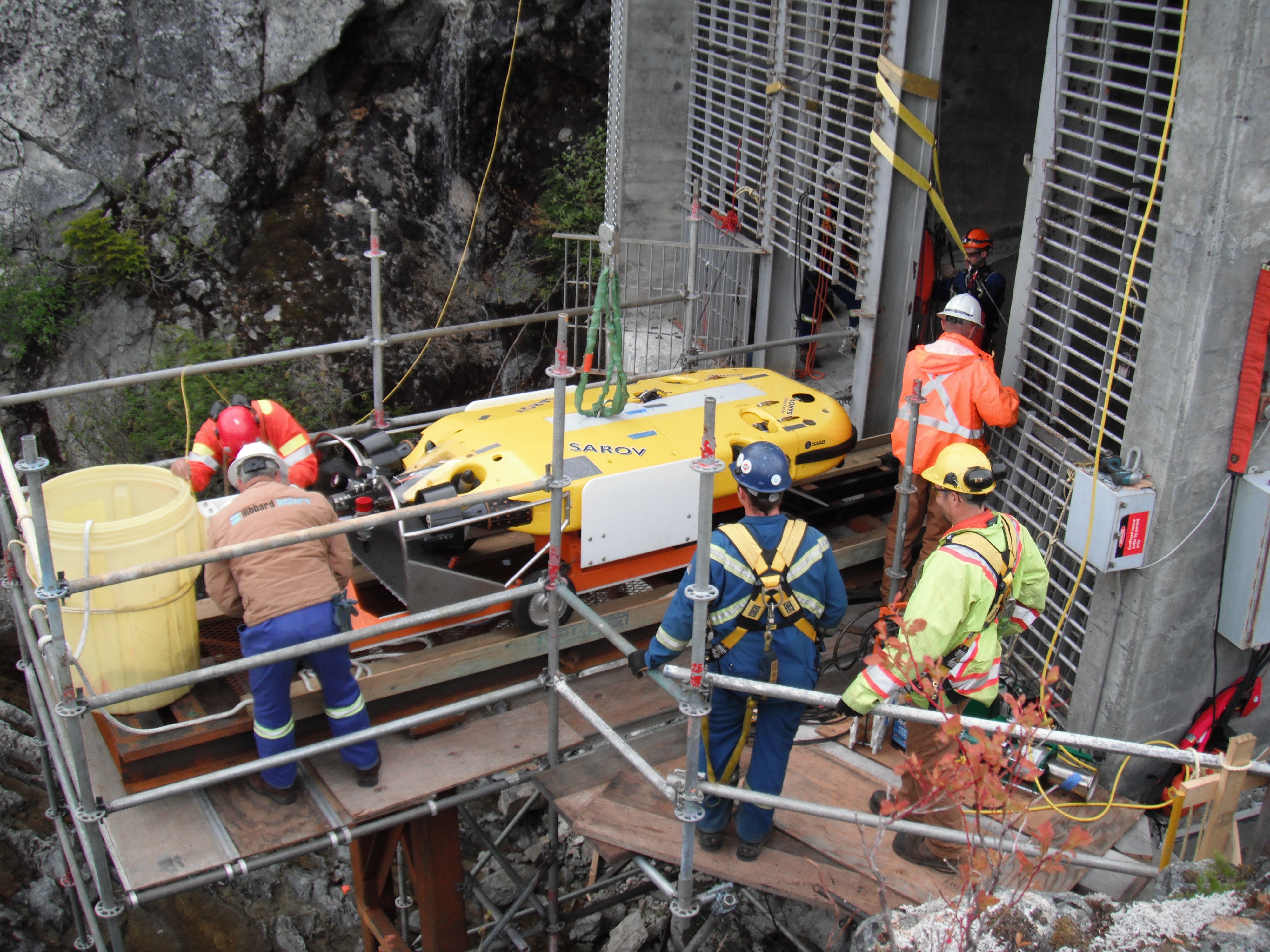
Figure 7:
Hibbard Inshore Long Tunnel Inspection Vehicle Entering Tunnel at Remote Job Site
Hibbard Inshore Sets the Standard for Inspecting Large Diameter Wastewater Trunk Lines.
Auburn Hills, MI, April 10, 2013:
Leading underwater service provider, Hibbard Inshore was put to the test when an inspection involving large diameter sewer lines presented itself. Located in Eugene Oregon, fully flooded siphons and partially filled interceptors were inspected for structural defects, sediment & debris accumulation, scour and other weaknesses.
Utilizing a customized floating ROV equipped with sonar units and cameras as well as a similarly equipped swimming ROV, Hibbard Inshore was able to inspect over 42,000 ft. of fully flooded and partially flooded sewer lines. The floating ROV was able to travel up to 5,000 ft. while navigating through bends and other complex parts of the structure, and the swimming vehicle was able to inspect the fully flooded siphon areas. Due to the capabilities of its equipment, Hibbard inshore was able to launch the vehicle in easy to reach access points while avoiding using manholes in more difficult to reach or heavily traveled, high traffic areas.
The customer stated that they were very pleased with the outcome of the project and the fact that a single sewer inspection company could address all of their difficult-to-inspect lines. With this success in inspecting larger diameter sewer lines and siphons, Hibbard Inshore hopes to continue to serve the wastewater industry by providing unique solutions.
About Hibbard Inshore
Headquartered in Auburn Hills MI, Hibbard Inshore is a global engineering services company
specializing in the use of Remotely Operated Vehicles (ROVs). With a premier fleet of ROVs and
experienced staff, Hibbard Inshore is able to provide the expertise and technology necessary to solve
the complex challenges of the inshore and offshore industry.
ROV Rock Trap Sediment Removal Survey, Trash Rack Repair Inspection and Temporary Bulkheading Investigation
Hibbard Inshore was contracted to perform several structural inspections at two hydroelectric power plants in order to accurately define the conditions of a surge shaft, a rock trap, a trash rack and two penstocks. The purpose of the inspections was that the penstocks, rock trap, and trash racks were all in locations that were under high head pressure, were difficult to reach, and the customer did not want to dewater the tunnels during the inspection or subsequent work operations as that process would be very costly and could be risky to the tunnels’ integrity. At the first plant, the main focus of the inspection was on the surge shaft, the section of tunnel downstream of the surge shaft including the rock trap, and a trash rack located inside the tunnel downstream of the rock trap. These structures needed to be accessed through the surge shaft. The rock trap that needed to be assessed for cleaning was at approximately 355 feet of depth as was the trash rack. At the second power plant the inspection was of the surge shaft, power tunnel, and on taking three dimensional underwater measurements of the penstocks and bifurcation area to determine whether temporary bulkhead plugs could be placed in each side to allow for the removal of turbine shut off valves.
 Surge Shaft for Access
At the first plant, the structures were inspected using the Navajo ROV equipped with dual sonar units and video cameras. The only access to the areas that required inspection was through the top of the surge shaft meaning that the ROV had to be hoisted to the top of the shaft and then lowered into the water. The invert of the tunnel was at A piece of conduit was found to be lying across the surge shaft and the ROV was able to identify areas of spalling with its video cameras. Upon entering the tunnel, the ROV was able to identify that a large amount of sedimentation and debris had completely covered the rock trap so that the divider walls could not be identified. Sonar measurements were taken along the length of the rock trap and compared to as-built drawings to determine the volume of debris present to allow for a ROV-based dredging plan to be put in place. At the downstream end of the rock trap, the trash rack was found to be severely damaged. The rack was made from several sections of steel bar and was anchored to a support beam that ran across the middle of the tunnel. The rack had failed as timber had lodged in between the bars of the rack and the subsequent pressure had likely caused the support beam and part of the rack to bend and fail. One section of the trash rack had moved down the penstock to a depth of 850 feet. The inspection allowed Hibbard Inshore to devise a method to use their ROVs for sediment removal in the rock trap, removal of the conduit in the surge shaft, removal of the damaged trash rack sections, and replacement of the trash rack. That work was completed in 2012, and is featured as a separate write up in the project gallery.
 ROV Video Capture Showing Trash Rack Failure
At the second plant, the inspection equipment also entered the tunnel through the surge shaft. Three areas with surface spalling were located in the surge shaft, and these features were cataloged with location. In the tunnel, the portion inspected was the 900 feet of tunnel downstream from the surge shaft to the bifurcation of the penstocks and then down each penstock. The tunnel was inspected in two passes. The first inspection pass was along the invert heading downstream. The second inspection pass was along the crown heading downstream. A spall was located on the invert of the tunnel approximately 195 feet downstream of the surge shaft. The ROV was able to dimension this spall to be 2.5 feet wide by 1.5 feet long and several inches deep. This was the largest spall or feature located inside the tunnel. A sonar close up was recorded to measure the depth of this feature to give the customer an accurate depiction. Other notable features found were pieces of conduit laying in the invert and the concrete to steel liner interface. Three pieces of conduit on the tunnel invert appeared to be pieces that were attached to the conduit on the surge shaft wall. All three pieces were laying on the invert in line with the flow. The furthest downstream piece of conduit had an unusually large end on the downstream end.
 Buckled Horizontal Trash Rack Support Beam
After inspecting that section of the tunnel, the bifurcation and penstock area were inspected in several phases. A visual inspection, 2D sonar cross section inspection and a 3D sonar inspection were performed. A number of features of interest were detected in addition to the dimensions. One penstock was inspected all the way to the scroll cage while the inspection of the other penstock ended at the valve because it was not fully opened. The ROV used its 3D and 2D sonar to image and dimension the penstocks to determine potential locations for temporary bulkheads. During that inspection, a drain was located on in the invert just upstream of the split in the penstocks and just downstream of the end of the tunnel. This drain was 1 foot in diameter and about 0.8 feet deep until debris was visible. However, during this phase of the inspection, the most important feature detected was a divider post upstream of the split in the penstocks. This vertical post divided the 8 foot tunnel in half and was several inches wide and about 1.5 feet long in line with the flow. This feature had not been on the as-built drawings. It was found that the two penstocks split off of the bifurcation and began to taper. There was an elbow in each penstock and just after this elbow was the location of the turbine shutoff valve. The Hibbard Inshore inspection was able to identify and dimension good areas for the temporary bulkhead plug placement. The plug placement and replacement of the turbine shut off valves will be performed in 2013.
 CAD of Typical Rock Trap Debris Found by ROV Inspection
In the past, due to the depth and confined locations, an expensive and risky dewatering would have been the only viable solution for these types of inspections and rehabilitations. Now, due to technological advances, some ingenuity and the experience at Hibbard Inshore, the inspections and maintenance work are entirely possible without removing the water from the structure.
Condition inspections at Multiple Dams
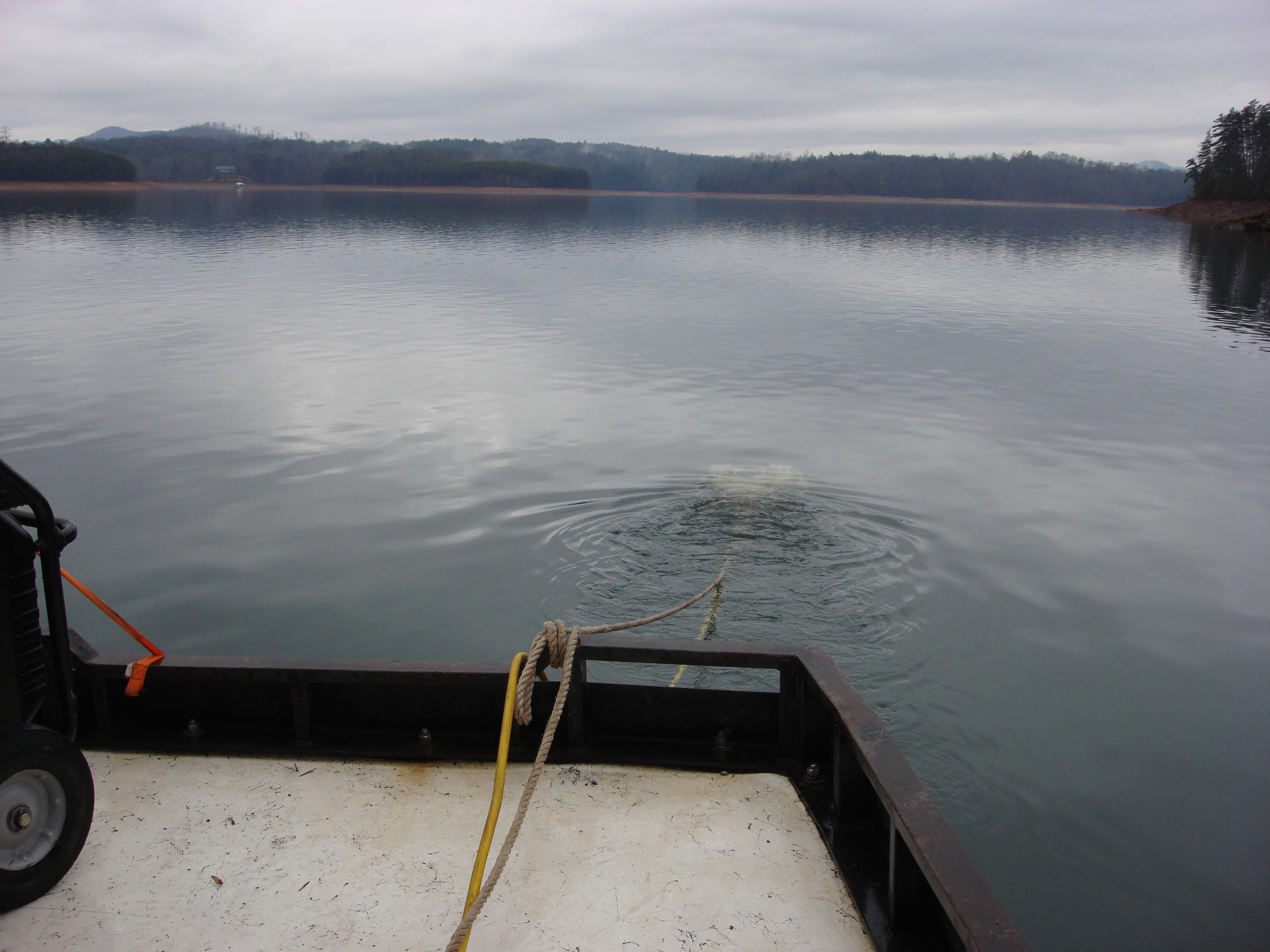
Hibbard Inshore was contracted to perform deep water inspections at 5 separate dams in the same region for a single owner over the course of 7 days. Hibbard used one of their Navajo (Link) swimming remotely operated vehicles (ROVs) with lights, dual sonar units and video cameras for the inspections. The inspections covered gate guides, trash racks, intakes, head gates, seal plates, roller plates, several valve operators, and the upstream face of two of the larger dams. The ROV was able to image these structures on both video and sonar with the latter helping to speed the face of dam inspections by scanning the entire face quickly so that visual confirmation could be performed only in areas of interest identified by the sonar.
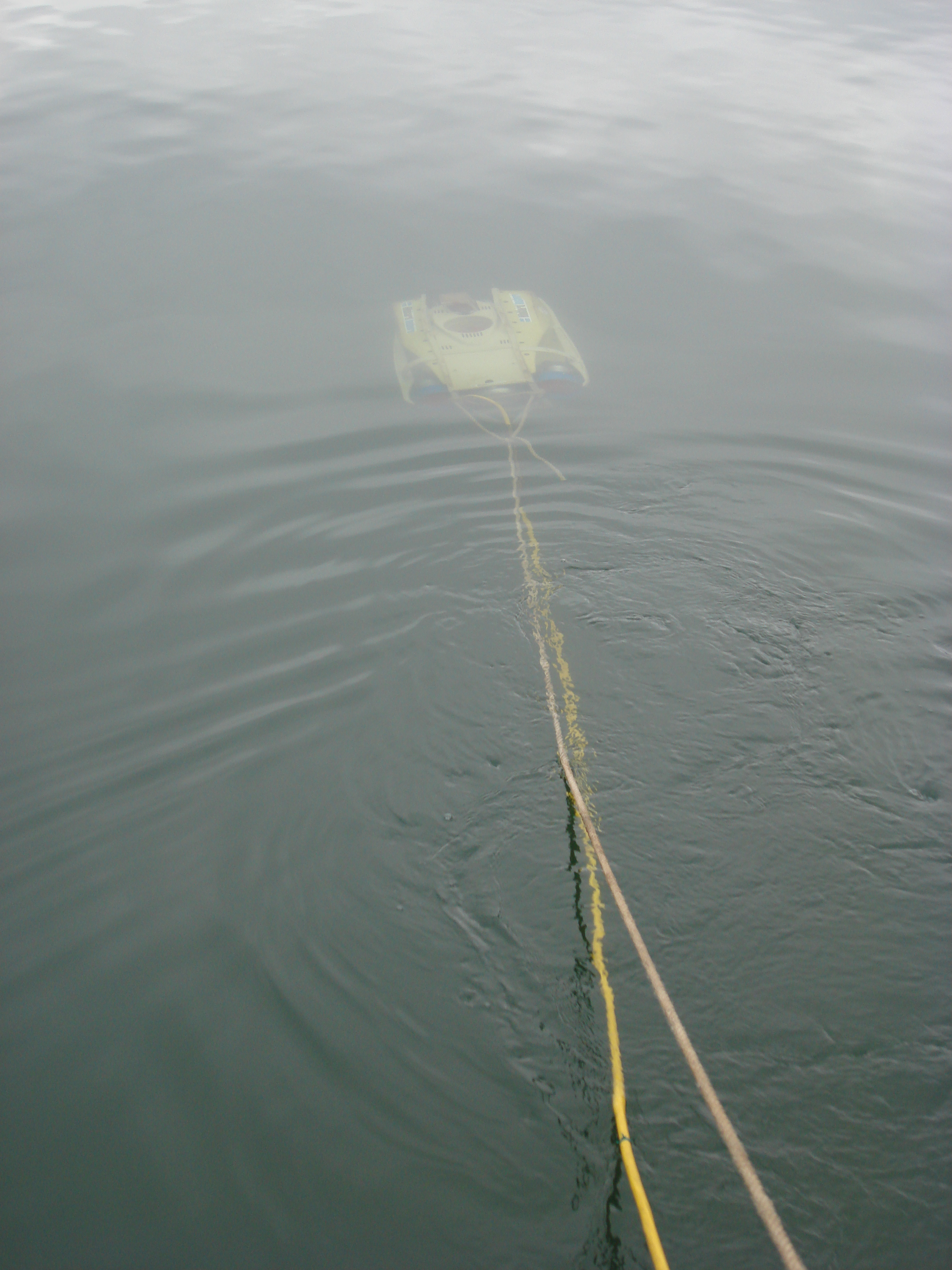
Following the completion of the inspection, all video inspection data and pilot notes were compiled into reports and delivered to client. The client then uses the data to form preventative maintenance plans, identify more immediate concerns, and to achieve regulatory compliance.
The primary advantages of the way these inspections were performed is that because Hibbard Inshore could provide several different equipment setups and techniques allowing for all of the various types of deep water inspection to be addressed at once, the customer could rely on them to complete, during a single mobilization, all of the services that they could not complete with their in-house equipment. This customer has created an Indefinite Delivery, Indefinite Quantity contract with Hibbard Inshore which allows them to schedule multiple inspections at standardized pricing. This allows them to group inspections together across their organization while still allocating costs to individual assets, and it allows several facilities to share in mobilization costs reducing the overall cost of inspection as a group.
ROV Cleaning of an Aqueduct Sump and Pouring of a Concrete Plug to Abandon a Shaft
A large city in the United States wanted to abandon a historical dewatering shaft adjacent to a shaft in one of their main aqueduct lines. The dewatering shaft communicated with the aqueduct shaft via a valve near the bottom of the sump portion of the aqueduct shaft, and the valve had ceased to operate over time. In order to abandon the dewatering shaft properly, the sump of the aqueduct shaft would need to be cleaned down to the concrete, and a concrete plug would need to be poured to close the existing valve. Once that plug was in place, the dewatering shaft could also be filled with a concrete pour. The difficulty in this situation is that the aqueduct shaft could not be dewatered, the water depth was over 300 feet deep, the shaft height was approximately 400 feet in total, and the shaft had a restriction such that it was too small for a commercial dive team to pass through with appropriate equipment to work at those depths.
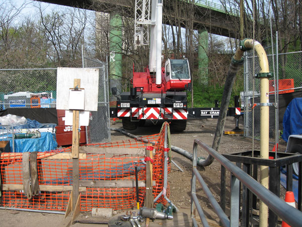
Hibbard Inshore developed a solution for their Mohican ROV with sonar and appropriate tooling to assess the sump, to clear the sediment and debris present, and to monitor the concrete pour of the plug in zero visibility conditions.
Hibbard started with a sonar and video inspection on the shaft to assess sediment buildup and debris. The large pieces of debris, including large timber, were then removed by the ROV using its manipulator arm and a variety of rigging. In addition to removing the large items, the ROV guided the suction hose of a high head pump that was able to remove the sediment in the sump to the surface where it was then transported to a permitted disposal site. The sump was monitored during the sediment removal by the ROV’s sonar to continually look at the sediment depth versus the as-built drawings to confirm that the sediment was fully removed.
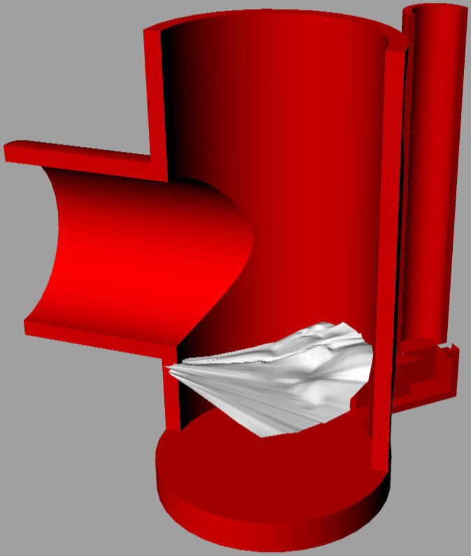
Following safe disposal of the sediment and debris, the trash pump was replaced with the equipment to pour the concrete plug. The ROV used its sonar to monitor the concrete placement in real-time as the plug needed to cover the entirety of the existing valve without restricting the lateral aqueduct pipe. This meant that the elevation of the plug pour had to be precise and the concrete pour would need to be cut off at exactly the right time to keep the pour elevation above the valve and below the invert of the lateral pipe (See CAD Model). The ROV allowed Hibbard Inshore to do this as the sonar could accurately measure the level of the pour as it was occurring.
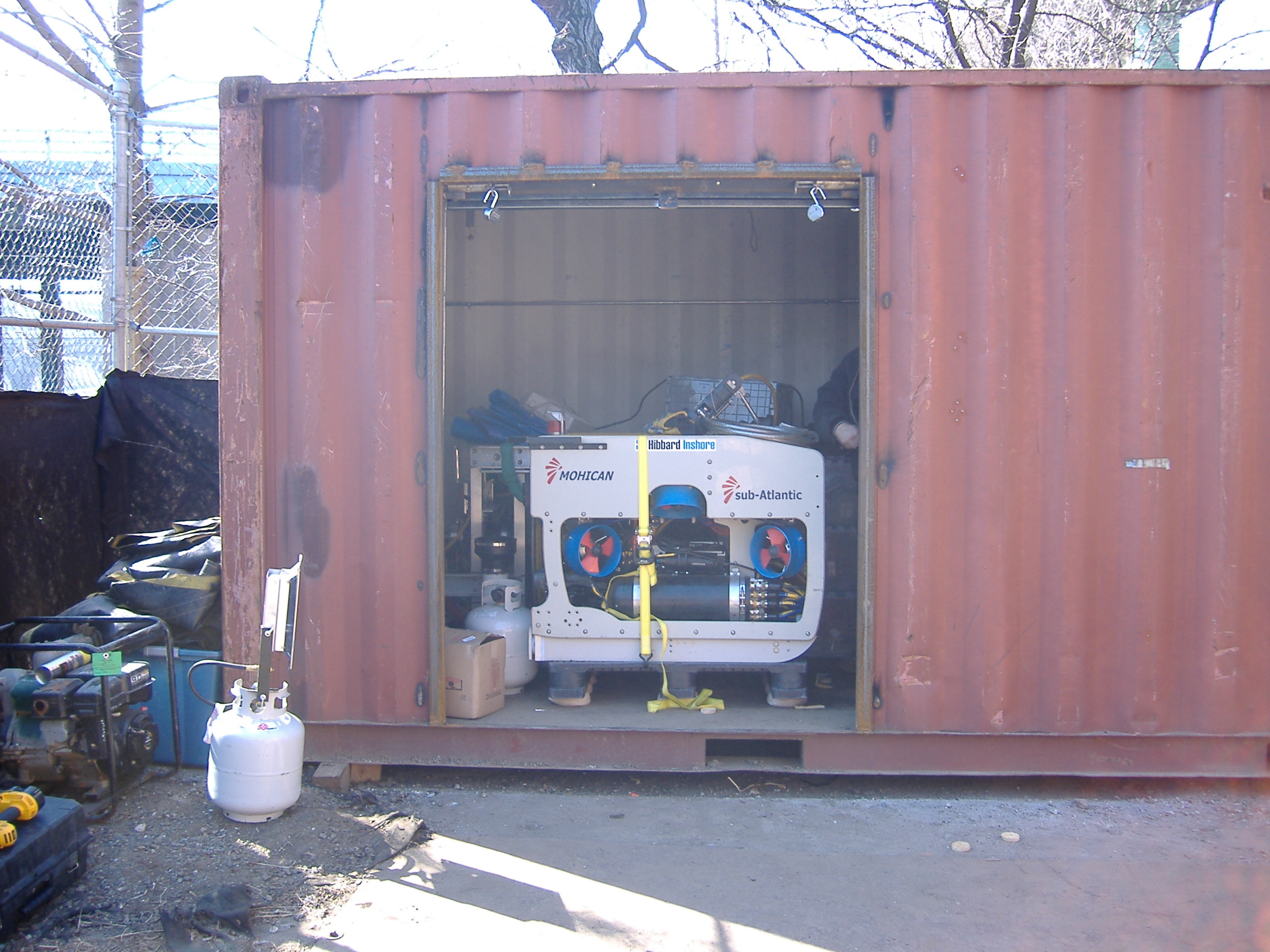
In addition to the concern about the plug height, the depth of the pour lead to a concern that the concrete would separate and not solidify. Because of this, Hibbard Inshore could not use a traditional tremie method to place the concrete and instead needed to devise a method to pump a mixture of concrete that would not separate. The concrete pour hose needed to be slowly extracted and maintain a precise height off of the bottom as the pour began to rise at the bottom of the shaft. Because the pour restricted visibility, the ROV’s sonar allowed the onsite crew to also coordinate the lifting of the concrete pour piping.
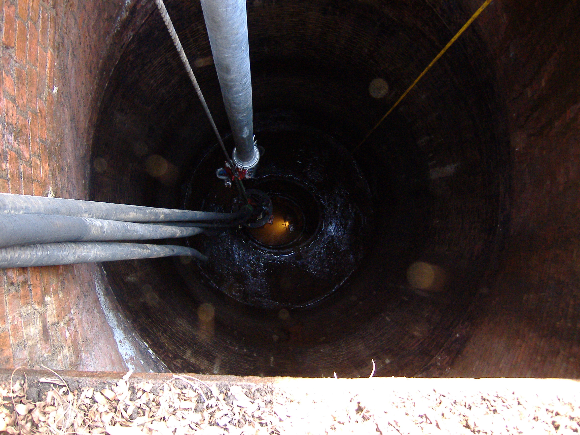
Finally, after the concrete plug was in place and had sealed off the valve connecting the two shafts, Hibbard Inshore was able to move the concrete pumping system to the adjacent dewatering shaft to complete a continuous 400 foot pour to completely fill and decommission that shaft. The inspection, dredging, debris removal and concrete services were all successfully performed by Hibbard Inshore, demonstrating the ingenuity of their team and the flexibility of their ROVs to perform a complex construction project in a deep water, confined space with limited visibility.
ROV Controlled Unmanned Dredging Adjacent to Active Intakes
Hibbard inshore performed an underwater survey and unmanned dredging project in front of units at a major pumping plant. The plant was due to change out each of its pumping units in favor of newer, more efficient models. In order to do this, when the existing units were removed, large amounts of silt and sedimentation from the canal would deposit in the intake area as well as the area where the new unit was to be installed. Because the client had to keep all adjacent units running during the replacement of each unit one by one, placing a diver in the water would have been extremely dangerous. So, having seen that Hibbard Inshore had run pumping operations with its ROVs previously, the client contacted them in order to develop a method and debris removal plan. Prior to arriving on site, Hibbard Inshore worked with the client to address a plan of action for the dredging project and analyze the infrastructure’s drawings to ensure the project could be performed safely and efficiently.
 Dredge Pump Ready to Lift
Hibbard Inshore’s ROV was equipped with video cameras, cross sectioning sonar, forward looking sonar, and a manipulator. The ROV was used to perform a sediment level measurement using its sonar, and then the ROV observed and guided the dredge pump during operations to ensure that all of the sediment was cleared. Before the removal began, Hibbard used its cross sectioning sonar to measure the sediment’s buildup. The cross sections taken from the ROV were compared to the plant’s drawing to determine the sediment buildup below. Following this, Hibbard Inshore maneuvered a dredging pump into the areas that needed cleaning and proceeded to clean the intake area. Sonar measurements were periodically taken throughout the project to check progress and ensure no sediment was missed. Sonar was important as the dredging process made it impossible to visually complete the process. With Hibbard Inshore’s experience in using sonar for navigation, feature detection, and measurement, that was not an issue. Hibbard Inshore successfully completed this dredging for each of several units that needed replacement over the course of a three year period allowing for each to be replaced with a new pumping unit successfully.. For the typical replacement of one of the units, Hibbard Inshore successfully dredged 168 cubic yards of sediment from the intake. To dispose of the sediment, Hibbard Inshore used a submersible pump and moved the sediment to a disposal area upstream. The ROV survey, sediment dredging and disposal typically required a total of four days per unit.
 Dredge Pump being Lowered for Debris Removal
This method increased project safety while maintaining project efficiency as neither the ROV nor the pump had any limit on bottom time and could run continuously. This method could be applied to any situation where deep water sediment and debris removal would be beneficial and currents or bottom time are a concern for the safety of divers.
Nuclear Power Plant Cooling Water Intake Inspection
 This photo shows the condition of the invert at 1470 feet. There were no significant debris or anomalies located in the search area past the 90 degree elbow.
A nuclear power plant identified a potential issue with a partial blockage in one of its cooling water intakes as it was not able to draw the volume of water that was expected. After trying several methods to locate the potential blockage without placing anything into the line, the customer determined that the best method for ultimately identifying a blockage and characterizing it for remediation would be to perform an internal inspection of the line with an ROV. At this point, they approached Hibbard Inshore. It was imperative that nothing interfere with the operation of this pipeline as it was a first line of defense in case of an overheating issue. Due to the critical nature of this cooling water pipeline, dewatering was not an option. Additionally, the length and many bends in the pipeline represented a definite safety risk in using a dive team. Hibbard Inshore was able to provide a small vehicle that could fit into the pipeline, carry both video and sonar, navigate the distance of the line, and perhaps most importantly could navigate the many bends with very low friction thereby reducing the risk of retrieving the vehicle.
To mitigate the safety risk and ensure that the Remotely Operated Vehicle (ROV) would navigate the bends in the pipe without risk of being stuck, Hibbard Inshore worked with the client to fabricate a pipeline of the same size with precisely the same bends the ROV would encounter in the actual pipeline. Usually, a demonstration of this sort is not necessary but due to the critical nature of the nuclear plant, it was requested and Hibbard Inshore had a direct analog to the existing pipe fabricated as a test stand for the vehicle. Once the test pipe was fabricated, Hibbard Inshore and the customer presided over testing where the force to haulback the vehicle was measured at strategic locations throughout the pipe. Hibbard Inshore demonstrated the ROV’s ability to maneuver the bends in the mock pipeline, and the customer determined that the risk would be low enough to use this method of inspection in the actual line at the facility.
 This picture shows the debris that had settled on the invert at 160′ from the Intake.
Once onsite, Hibbard Inshore worked with a commercial dive team to mitigate the risk to the ROV and umbilical. The dive team secured a sheave on the intake to assist the ROV and umbilical in order to reduce friction and monitoring the umbilical from in front of the intake. For this inspection, Hibbard Inshore chose to used their LBV600-6 ROV (Link) due to its sensor configuration, small size and long range capability. The thrust of this swimming ROV provided the necessary ability to maneuver in the pipe while negotiating the bends and pulling the umbilical over long distances. The ROV was outfitted with a color video camera, a low light B&W camera, sector scan sonar and profiling sonar. The sector scan sonar unit was used for feature detection and navigation through the pipe while the profiling sonar dimensioned the pipe cross section.
During the official inspection, Hibbard Inshore’s pilots successfully navigated all the bends, traveling 1851 feet of the pipeline and profiling the interior surface in its entirety. The customer was happy with the ability to see the pipeline’s internal conditions and to determine with certainty any areas for future maintenance. Due to the success of the project, they have approached Hibbard Inshore on additional inspections of similar nature.
Offshore Sensor Placement and Retrieval
This job was completed for a customer in the Scientific Research Industry and involved the location and retrieval of subsea sensor pods. These pods were in several hundred feet of water and had an issue where the attached acoustic buoy systems would not release and surface to allow retrieval. Because of this, the customer could not retrieve their sensors from the ocean bottom without assistance. Knowing that Hibbard Inshore had a variety of ROVs, the customer called Hibbard Inshore looking for a suitable ROV and crew to mobilize quickly to assist the retrieval. Hibbard Inshore was able to keep costs manageable by using a small but powerful swimming ROV fitted with sonar, a manipulator arm and a USBL positioning system to locate each sensor pod and attach to it for retrieval. Once the pods were brought to the surface, and the customer downloaded the data, the ROV was used to help precisely replace the sensors on the ocean floor. The ROVs live video and positioning system ensured accurate placement and orientation of the modules as they were redeployed to the sea floor for additional data collection.


 Inspections
